Internal structure of electronic load
The basic workings of electronic loads, which play a very important role in the design and production of power products, seem to have remained shrouded in mystery until now. Constant current control is the basis of
electronic load, the core essence of the circuit is the current sampling negative feedback control loop, transistor Q1 as a current control device, but also as the load measured power supply. Transistor Q2 is the push-tube of Q1; Resistor R1 is a current-to-voltage converter (I/V converter). The voltage drop on R1 is compared with the reference source (Verf) by a voltage comparator IC1 to control the on-off and on-off of Q2 and Q1 to keep the current constant.

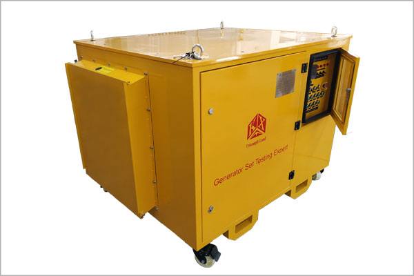
500kw load bank
The working principle of electronic load is to control the internal power MOSFET transistor or conduction duty ratio size (number), power tube energy consumption, it can accurately detect the load voltage, accurately adjust the load current, at the same time can realize the simulation of load short circuit, simulation of load is inductive or capacitive, capacitive load current rise time. Debugging and testing of general switching power supply is essential.
Electronic load can simulate the load in the real environment (with electrical appliances), generally strict requirements for power supply manufacturers will use electronic load to detect the quality of power supply. It has many functions, can adjust the load size, as well as short circuit, overcurrent, dynamic and so on.
